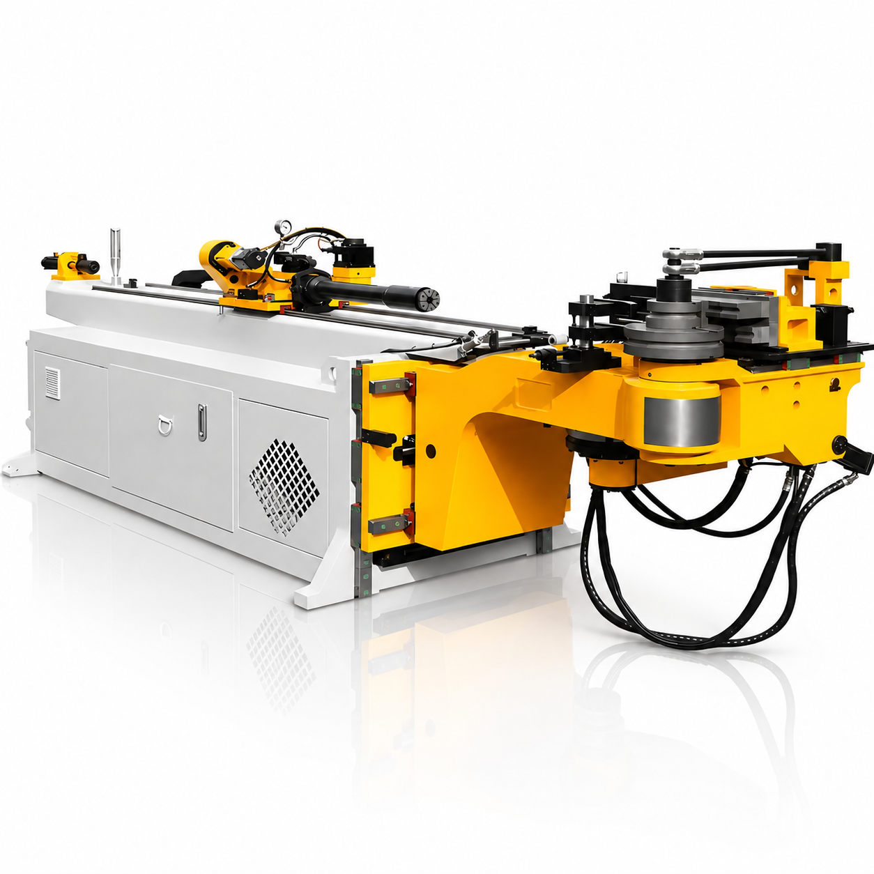
63 CNC Single-Head Hydraulic Tube Bending Machine
- Ø63 × 6 mm maximum bending capacity: Accommodates tubes up to the listed outside diameter and wall thickness, subject to material and tooling requirements.
- 30–300 mm bending radius range: Supports different tube geometries with suitable bending dies.
- Maximum bending angle of 190°: Provides angular travel for a range of bend configurations.
- Coordinated CNC movements: Controls bending, tube rotation, and feeding for parts with multiple bends.
- Touchscreen operation: Provides an accessible interface for setting up the bending process.
- Servo-driven feeding and rotation: Supports controlled tube positioning between bends.
1S0 9001
Certiffed
SVG
Certiffed
CE
Certiffed
Global
Support
Product Features & Details
CNC Control for Multi-Bend Tube Components
The machine coordinates bending, tube rotation, and feeding to produce tube components with bends at different positions and orientations. These movements allow the tube to be repositioned between bends according to the required part geometry.
The touchscreen provides an interface for machine setup and operation. Controller functions, program capacity, and available programming methods should be confirmed for the selected configuration.
Single-Head Hydraulic Bending Unit
The single bending head uses dedicated tooling to guide the tube through the forming operation. Hydraulic power supplies the bending movement, while the clamping arrangement holds the workpiece in position.
The specification lists a maximum bending angle of 190° and a bending speed of 30°/s. The usable bend angle for a particular part also depends on tooling clearance and interference between the formed tube and the machine.
Ø63 × 6 mm Listed Bending Capacity
The supplied technical sheet lists a maximum tube size of Ø63 × 6 mm, representing outside diameter and wall thickness.
This capacity should be evaluated against the actual tube material and bend requirements. Material strength, wall thickness, bending radius, and tooling all affect the forming load and finished tube quality. Submit the material specification and part drawing when requesting a capacity check.
Servo-Driven Tube Feeding and Rotation
The machine uses separate servo motors for feeding and rotation. The specification lists 1.5 kW feeding servomotor power and 1 kW turning servomotor power.
Tube feeding positions the workpiece along its length, while rotation establishes the orientation of the next bend. Coordinating these movements supports the production of components with several bends in different planes.
The listed feeding speed is 800 mm/s, and the turning speed is 160°/s. Actual cycle time depends on travel distances, bend sequence, clamping, and operator handling.
Positioning Precision for Consistent Forming
The technical sheet lists:
- Bending precision: ±0.10°
- Turning precision: ±0.10°
- Feeding precision: ±0.10 mm
These figures describe the listed machine positioning performance. Finished-part dimensions also depend on material springback, tube variation, tooling condition, and process setup.
For tolerance-sensitive components, sample bending and inspection can establish the settings required for the intended material and geometry.
Tooling and Clamping Arrangement
The supplied images show a bending unit, clamp structure, and forming tooling. These components work together to hold the tube and guide it around the bending die.
Tooling must match the tube diameter, section, and required radius. Requirements for internal support or additional forming tools should be reviewed according to wall thickness, radius, and acceptable deformation.
Applications Across Tube Fabrication
The supplier identifies applications including automotive parts, furniture frames, construction hardware, fitness equipment, and custom tube fabrication.
The machine is intended for components that require controlled bend positions and orientations. Part feasibility should be checked for minimum straight lengths, clamp space, feeding clearance, and interference throughout the bending sequence.
Technical Parameters
| Parameter | Listed Specification |
|---|---|
| Machine type | CNC single-head hydraulic tube bending machine |
| Maximum bending capacity | Ø63 × 6 mm |
| Bending radius range | 30–300 mm |
| Maximum bending angle | 190° |
| Bending speed | 30°/s |
| Turning speed | 160°/s |
| Feeding speed | 800 mm/s |
| Bending precision | ±0.10° |
| Turning precision | ±0.10° |
| Feeding precision | ±0.10 mm |
| Turning servomotor power | 1 kW |
| Feeding servomotor power | 1.5 kW |
| Effective distance, as listed | 2,600 mm |
| System motor power | 7.5 kW |
| Maximum hydraulic pressure | 16 MPa |
| Packaging dimensions, L × W × H | 5,000 × 1,200 × 1,350 mm |
| Machine weight | 3.5 t |
Final specifications depend on the confirmed model and configuration.
Customization Options
The listing offers the following services, each with a minimum order of one set:
- Customized logo
- Customized packaging
- Graphic customization
For an application-specific quotation, discuss:
- Tube bending dies: Specify tube diameter, wall thickness, material, and bending radius.
- Clamping and support tooling: Provide minimum straight lengths and acceptable tube deformation.
- Controller requirements: Confirm the required programming functions and operating interface.
- Electrical supply: Specify site voltage and frequency.
- Part acceptance requirements: Define dimensional tolerances and sample inspection criteria.
Availability of machine and tooling changes should be confirmed with the supplier.
FAQ
What does Ø63 × 6 mm mean?
It describes the listed maximum tube outside diameter of 63 mm and wall thickness of 6 mm. Applicability must be checked for the specific material, radius, and tooling.
Can the machine produce bends in different planes?
The supplied description identifies coordinated bending, rotation, and feeding. Tube rotation allows subsequent bends to be made in different orientations, subject to part clearance and tooling limitations.
What bending radii are available?
The listed range is 30–300 mm. Each required radius must be matched to suitable tooling, and the supplier should confirm how the radius is defined.
Does the listed precision guarantee finished-part accuracy?
The stated figures describe machine positioning performance. Finished-part accuracy also depends on material springback, tooling, and setup. A sample test is useful for confirming a particular tolerance.
Is tube loading and unloading automatic?
The screenshots do not establish an automatic loading or unloading system. Confirm the handling equipment included in the quotation.
What information is needed for a quotation?
Provide the tube material, outside diameter, wall thickness, part drawing, bending radii, bend angles, dimensional tolerances, and expected production volume.
What inspection documents and warranty are listed?
The attribute table states that a machinery test report and outgoing inspection video are provided, together with a one-year warranty. Confirm these terms for the final machine model.
Support & Service
- Configuration review: Submit tube drawings to discuss machine capacity, bend feasibility, and tooling.
- Inspection documentation: Request the listed machinery test report and outgoing inspection video.
- Warranty: Confirm the stated one-year warranty coverage and service arrangements.
- Installation information: Request electrical, hydraulic oil, floor-space, and installation requirements.
- Operating documentation: Request the controller manual, tooling setup instructions, lubrication schedule, and spare-parts information.
Send your tube specifications and part drawings to request a confirmed machine configuration and quotation.